+86 13110089902
 bella.zhang@free-optic.com
How to Use Laser Marking Machine
December 18, 2025
Introduction to Using a Laser Marking Machine
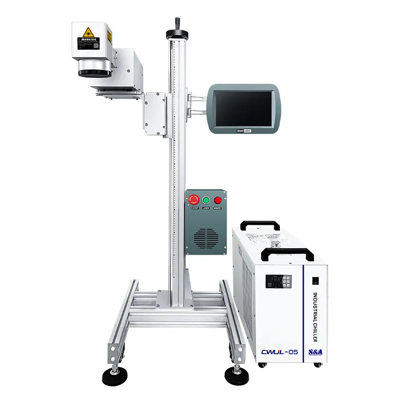
A Laser Marking Machines is a precise tool used to engrave or etch logos, serial numbers, barcodes, and designs on various materials including metals, plastics, and ceramics. Understanding how to use it correctly ensures accurate, high-quality marks and prolongs the life of the equipment.
Before starting, it helps to know what is a laser marking machine and how it works. Laser marking offers advantages over traditional marking methods, including speed, durability, and minimal material damage.
Operating a fiber, CO2, or UV laser marking machine for the first time can feel overwhelming. From configuring the software parameters to aligning the focal length, a single incorrect setting can lead to blurry engraving or, worse, damaged materials.
Whether you are running a high-speed production line or operating a desktop workshop laser, this comprehensive guide from Free-Optic will walk you through how to use a laser marking machine safely and efficiently in 5 simple steps.
Pre-Operation Checklist: Safety First
Before flipping the power switch, ensure your workspace meets industrial safety standards:
- Wear Laser Safety Glasses: Ensure your goggles match the specific wavelength of your machine (e.g., 1064 nm for Fiber lasers). Never look directly at the laser beam.
- Turn on the Fume Extractor: Laser marking generates micro-particles and fumes. Always operate your system with a dedicated ventilation or filtration unit.
5 Steps to Operate Your Laser Marking Machine Perfectly
Step 1: Powering On the System Correctly
Always follow the manufacturer’s strict sequential power-on protocol to prevent electrical surges:
- Turn on the main Mains Power → Switch on the Chiller/Cooling System (for UV/CO2) →Turn on the Laser Source Key Switch → Launch your computer and control software.
Step 2: Importing Designs and Setting Up Software (EZCAD)
Most industrial marking machines utilize EZCAD or LightBurn software.
- Import your vector file (
.DXF,.AI,.PLT) or raster image (.JPG,.BMP). - Position the artwork within the software’s workspace marking grid.
- Apply the hatch fill settings (Line spacing usually set between 0.03nm – 0.05nm for smooth metal engraving).
Step 3: Calibrating the Precision Focal Length (Crucial!)
If your laser is out of focus, it will either fail to mark or produce weak, discolored burns.
- Use the machine’s dual red-dot alignment system.
- Mechanically raise or lower the Z-axis lifting column until the two red dots perfectly merge into one single dot on your material’s surface. This indicates your laser is at its optimal focal point.
Step 4: Configuring Power, Speed, and Frequency Parameters
Different materials require drastically different laser recipes. For a standard $30\text{W}$ Fiber Laser, use these baseline parameters:
| Material Type | Speed (mm/s) | Power (%) | Frequency (kHz) | Marking Goal |
| Stainless Steel | 500 – 800 | 40%–60% | 30 – 40 | High-contrast black etching. |
| Aluminum | 1000 – 1500 | 50%–70% | 20 – 30 | Clean white surface frosted finish. |
| Rigid Plastics (ABS) | 1500 – 2000 | 15%–30% | 40 – 50 | Fast, crisp surface marking without melting. |
Step 5: Executing the Test Run and Final Marking
- Activate the Red Light Pointer (F9) to project a safe visible red bounding box onto your material. Adjust the physical placement of your object.
- Once aligned, hit Mark (F2) to execute the actual laser fire.
Troubleshooting 3 Common Operation Errors
- Problem: The laser fires, but there is no mark on the metal.
- Solution: Re-check your focal length. A deviation of just 2 mm can cause zero power transfer.
- Problem: The edges of the engraved logo look blurry or warped.
- Solution: Your software field size might not match your physical field lens specifications (e.g., trying to mark a 200×200 mm file with a 110×110 mm lens).
- Problem: Plastic material is melting or burning yellow.
- Solution: Your power is too high or speed is too slow. Drastically increase the marking speed and drop the power below 20%.
Need Expert Parameter Settings for Your Unique Material?
Different alloy compositions and composites require specialized fiber pulse widths or UV wavelengths. Stop wasting expensive material samples on trial and error.
[Contact Free-Optic’s Technical Support Team] — Upload your material specifications or send us a sample. Our application engineers will test-mark it in our lab and send you the exact EZCAD parameter template file for free!